The batteries used for the backup voltage for the real time clocks and SRAM settings in vintage computers are a real nuisance today. These were used in nearly all personal computers back in the 80s and beginning of the 90s and every single one started to leak and damage the PCB of the surrounding system. In the Amiga 500 they are used for the clock on trapdoor memory expansions. If you have one with such an ancient battery, it should be removed immediately. Here I describe, how a standard CR2032 coin cell holder can be fitted in place of the old battery to keep the clock running.
You need: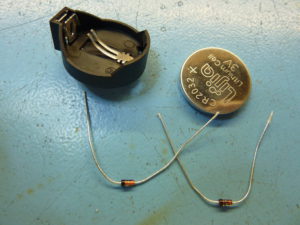
- CR2032 battery
- CR2032 cell holder
- 2xBAT42 Schottky-diode
- Soldering iron
- Solder wick
- Multimeter
The theory:
Look at the schematics for the backup power supply for the RTC. This is the typical circuit found on many trapdoor cards. The parts might have different designators though:
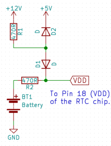
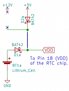
This circuit ensures that if AC power is present, VDD is at 5V and if not, that VDD gets the full battery voltage and that the battery is not feeding back into the 5V rail of the Amiga. In some cases R2 is omitted and R1 might have a different value. When replacing the battery with the button cell, we must also remove this charging circuit. In addition, the supply from battery to Pin 18 of the RTC must be established. We must produce a circuit that looks like this:
The modification:
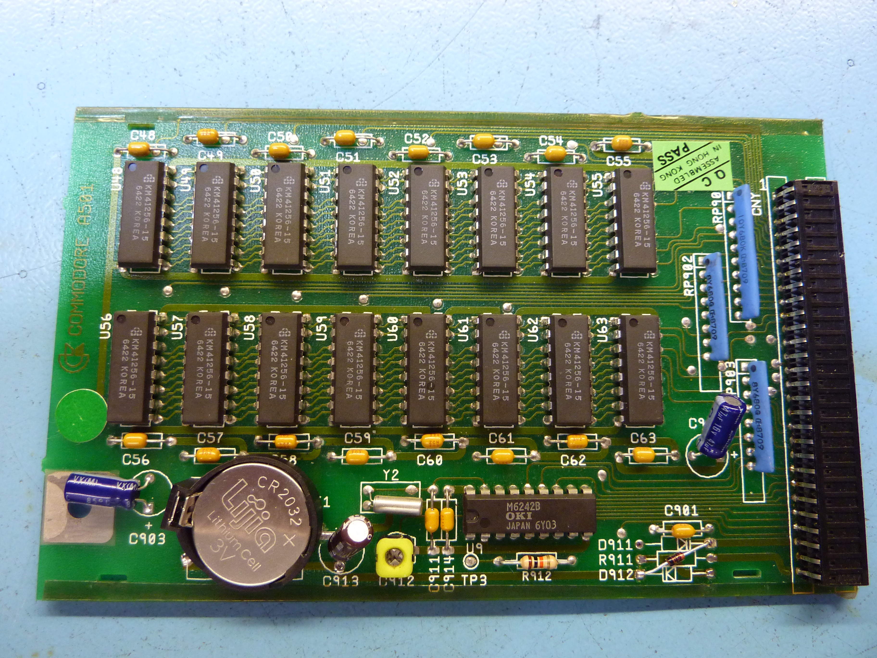
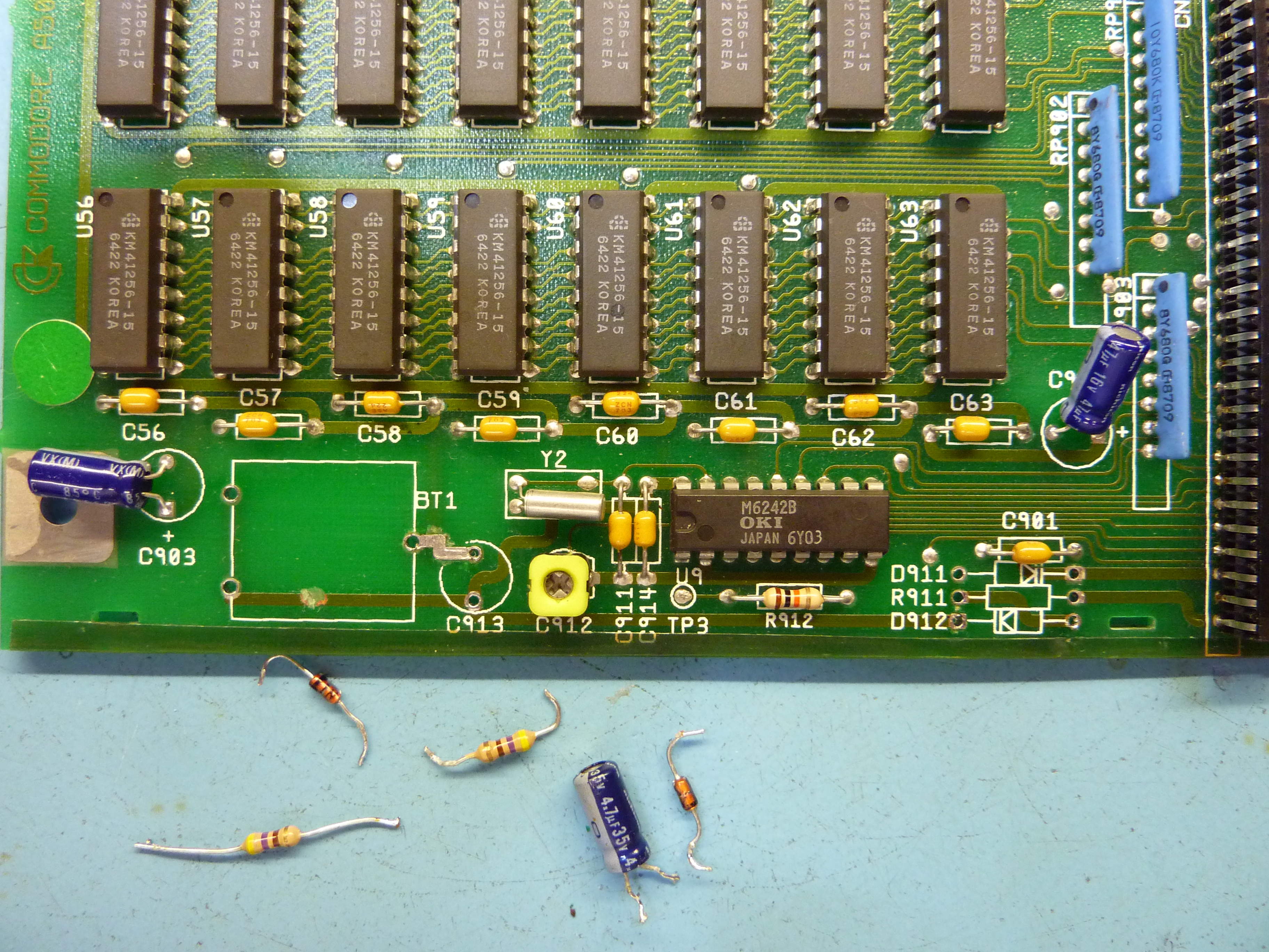
Start by identifying the RTC (the Chip marked M6242), R1, R2 and the two diodes. They are usually close to the RTC as in the following example. Usually it is similarly obvious what is what. If you are in doubt, you will have to buzz out the circuit. Start with the diodes.
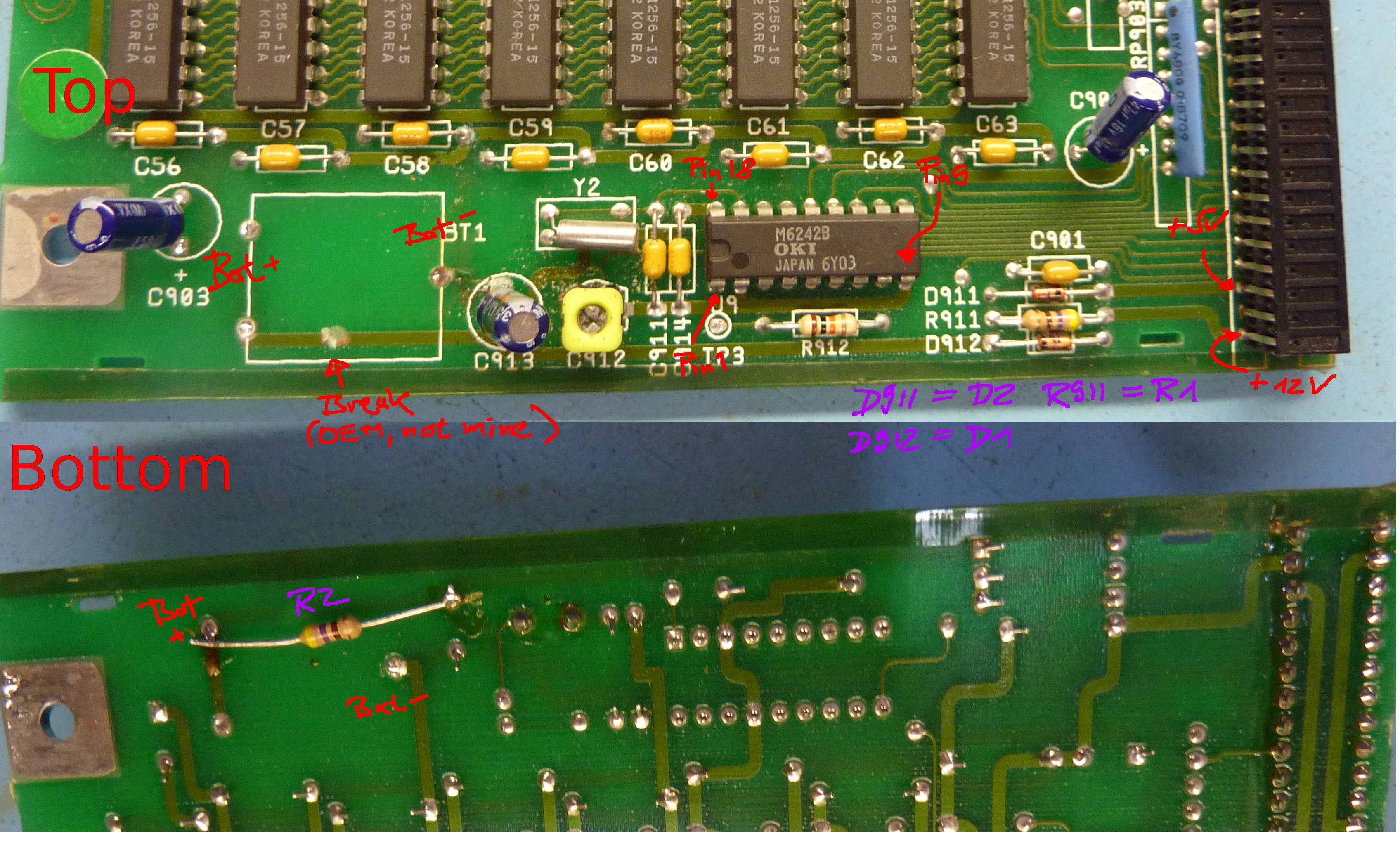
If the RTC is in a socket, then remove it for safety. Desolder R1, R2, D1, D2 and the old battery. If R2 is not present, cut any direct connection between the positive Pad for the battery and Pin 18 of the RTC.
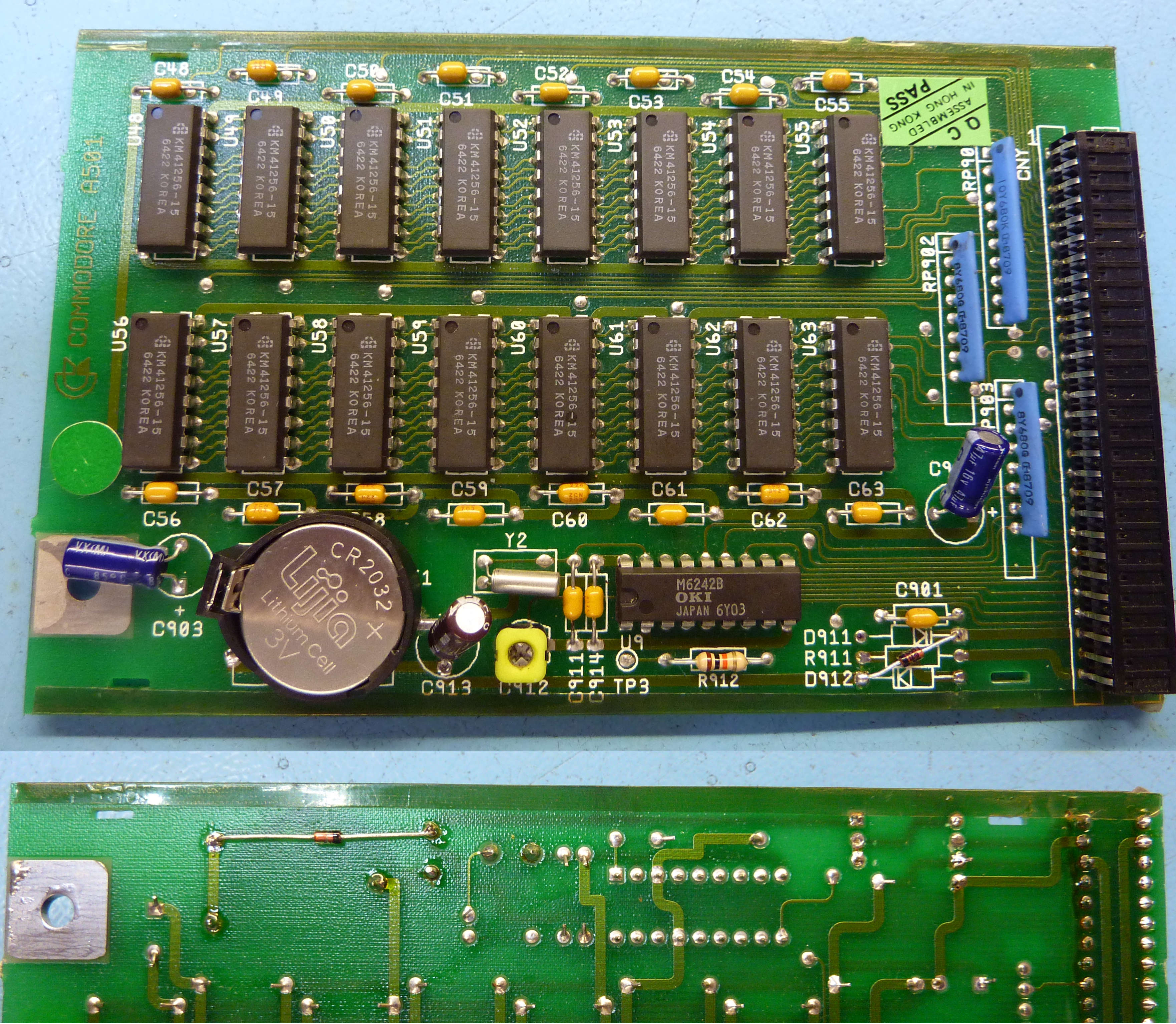
Put in the first Schottky-Diode BAT42 in reverse to the original diode D1 and the second BAT42 replaces R2. For D1 you solder a jumper link. Solder the coin cell holder with the correct polarity. That’s it.
Testing / Troubleshooting:
If you removed the RTC do not yet put it back. Insert a lithium cell into the cell holder and measure the voltage between pins 9 and 18 of the RTC or its socket. With a fresh CR2032 cell, it should be near +3V plus/minus 0.2V. If not:
- check polarity of the lithium cell holder and the cell
- check polarity of D1a
- check that the negative of the cell is connected to pin 9 of the RTC
- check the connection between the cathode of D1a and pin 18 of the RTC
Install the expansion in an Amiga and power on. Now the voltage between pins 9 and 18 of the RTC or its socket should be near +5V. If not:
- check the polarity of D2a and its connections to +5V and pin 18 of the RTC
If everything is fine, switch off your Amiga and put the RTC back into its socket (mind the polarity) and set the clock. It should work now as designed.
Please leave a comment if you like this post.