Here is a small project that I wanted to get dob for quite a while. It is a little PCB that can be used to swap how the Amiga sees the floppies. In one state everything is normal, and if a jumper is set, then DF0: and DF1: are swapped, so that you can boot from an external floppy drive.
What makes this design differ from other designs is that it is controlled by a single jumper or a normal STSP switch. This makes it controllable via the Key-Tap, another one of my little projects.
How it works
A Floppy drive is controlled by a bunch of electrical signals, among which one signal is the most important, it is called /SEL. If this line is high, the drive ignores all other control signals, and if it is low, it responds to them. In the AMIGA, the even CIA chip generates four select signals /SEL0 – /SEL3 responsible for the drives DF0: to DF3: To swap the floppy drives we can electrically swap the /SEL0 and /SEL1 line and the AMIGA will not be aware that we changed its view of the world. In simple Floppy swapper PCBs this is simply done with a clever (DPDT) switch arrangement. Here we choose a dual 4-channel multiplexer chip 74HCT153 (here is the Nexperia datasheet) to do the work. While it seems overkill to use an IC where a simple switch would do, this has some advantages:
- We can control the multiplexer by one signal. This control signal is much simpler: If we ad a pull-up resistor it is sufficient to either let the signal be pulled up for one state or connect it to GND via a jumper or a SPST switch to get into the other state. Furthermore this signal can be generated by the Key-tap so that you do not need a mechanical switch at all.
- The select lines do not have to be run via long connections to a switch and back. This reduces the risk of short circuits, noise pickup and possible damage to the CIA.
- The 74HCT153 and a SPST switch is actually cheaper than a DPDT swich.
The main disadvantage is that you can not realize this circuit without a PCB. Fortunately, here is my design which you can use freely. KiCad schematics, PCB and the resulting Gerbers are in my Github repo here:
https://github.com/jmA500/amiga-goodies
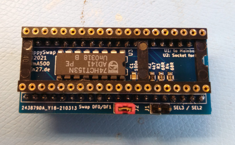
Look into the folder floppyswap for the files for this project. I used the gerbers in amiga-goodies/floppyswap/Gerber/floppyswap-20210313-0042.zip to produce the PCB in the image above. Building it should be straigtforward, you need only a couple of passives, the socket for the CIA and pin headers to connect to the socket of the even CIA.
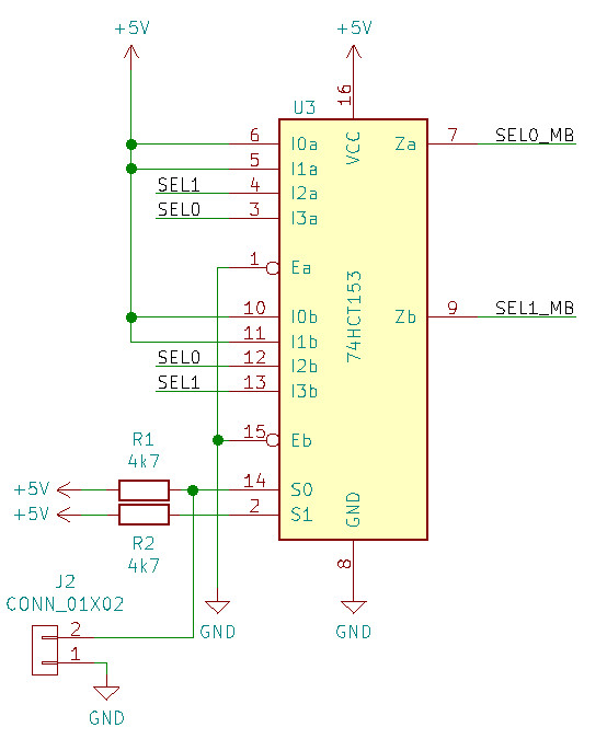
Look at the schematic above. The lines SEL0 and SEL1 are coming from the CIA. Since Eb and Ea are grounded, both outputs of the multiplexer are always enabled. Channel a controls the line connected to the internal DF0: and Channel b the select for the first external drive. The binary representation of the input at S0,S1 selects which input of the multiplexer gets connected to its output. Since we want the swapper to be inactive if the jumper is unset, the multiplexers are connected, so that SEL0 and SEL1 are unswapped if S0 is high (I3a and I3b are connected to Za and Zb respectively) , and swapped if S0 is low.
If you have a PCB, building and using should be straight forward. You only need a few passives together with the multiplexer and socket plus pin header for the CIA and connection to the Mainboard. All parts are in this list at reichelt.de.